Deploy L3VPN Services for Customer 4
Preparing The Lab
- Log into the LabAccess jumpserver:
- Type
labs, or select Option 97 to get to theAdditional Labsmenu. - Type or select the option for
mesh-topology-evpn-labsin order to get to the EVPN labs. - Type
c4l3vpnin this menu to configure the topology with the necessary prerequisites.
- Type
Lab Tasks
-
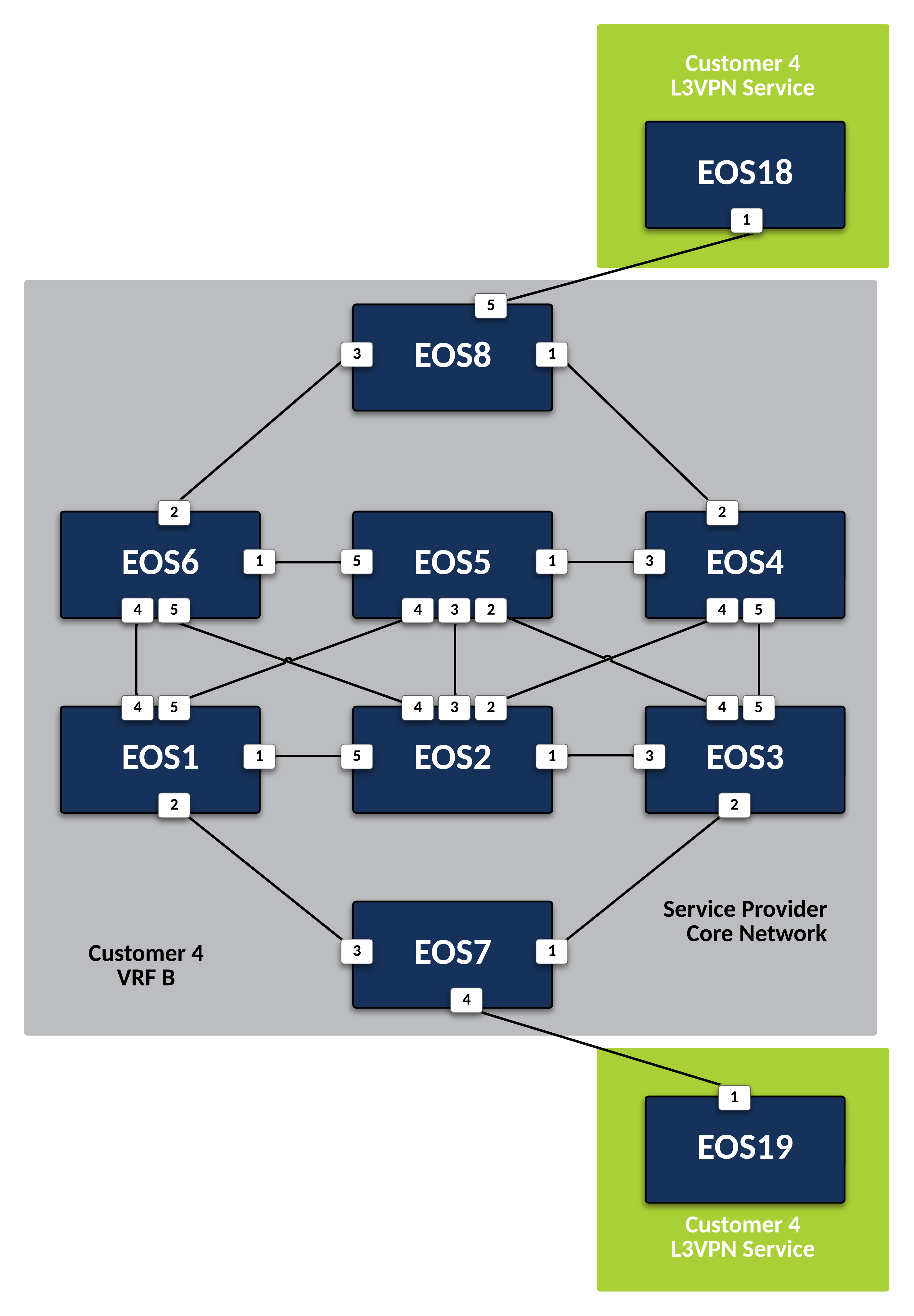
Customer-4 is attached to two Service Provider nodes,
EOS7andEOS8. These will be our PE nodes. Since this customer will require a Layer 3 VPN Service, create an isolated VRF for their traffic and use EVPN to advertise the customer networks to other interested PEs.-
Create a VRF Instance called CUSTOMER-4 on
EOS7andEOS8.Note
The steps in this lab will be similar to the Customer-1 L3VPN lab, demonstrating the repeatable nature of an EVPN deployment, which can easily be automated with CloudVision once the concepts are understood.
-
Place the interface attached to the CE node for Customer-4 into VRF CUSTOMER-4 on
EOS7to ensure their traffic remains isolated. -
Repeat the above step for the interface on
EOS8attached to Customer-4 CE device. -
Now leverage BGP EVPN to advertise reachability of any routes learned in VRF CUSTOMER-4 from the customer by setting an RD and an RT, within BGP on
EOS7andEOS8. It should have a unique RD following the format of Loopback0 IP:4 and the RT on all routers in the VPN should match as 4:4.EOS7
router bgp 100
    !
    vrf CUSTOMER-4
        rd 7.7.7.7:4
        route-target import evpn 4:4
        route-target export evpn 4:4
EOS8
-
Finally, define the BGP peers facing the CE devices for route exchange into the customer VRF on
EOS7andEOS8. The CE nodes (EOS19andEOS18) will use BGP ASN 200.EOS7
router bgp 100
    !
    vrf CUSTOMER-4
        neighbor 10.7.19.19 remote-as 200
        neighbor 10.7.19.19 maximum-routes 12000
        !
        address-family ipv4
            neighbor 10.7.19.19 activate
EOS8
-
Verify configurations and VRF status. There will be no routes or BGP peers in our VRF as of yet since we have not peered with the CE devices.
-
-
Now that the PE nodes are configured, configure CE nodes
EOS18andEOS19for Layer 3 attachment to the Service Provider network.-
Configure the BGP peerings to the PE devices on
EOS18andEOS19ensuring that each router’s Loopback0 address is advertised to the attached PE.Note
Since both CE devices are using BGP ASN 200, we need to ensure BGP allows the router’s own ASN in the AS-PATH, which normally is marked as an invalid route, with the allowas-in option.
EOS18
router bgp 200
    router-id 18.18.18.18
    neighbor 10.8.18.8 remote-as 100
    neighbor 10.8.18.8 allowas-in 1
    neighbor 10.8.18.8 maximum-routes 12000
    network 18.18.18.18/32
EOS19
-
Testing
-
With the peerings fully established, verify and test connectivity between the Customer-4 locations.
-
Verify BGP status and route exchange with the Service Provider network on
EOS18. -
Test connectivity from
EOS18toEOS19using Loopback0 IP addressing.
-
-
From the Service Provider nodes, verify route exchange and MPLS control-plane status.
-
Display the peering status and routes being advertised by
EOS18onEOS8. -
Now validate the EVPN routes are exchanged between the PE nodes
EOS7andEOS8via the Route Reflector. -
Finally, validate the forwarding path traffic will take for each destination in the customer VRF on the Service Provider network PEs
EOS7andEOS8.
-
Success
Lab Complete!