CloudVision Studios - Layer-2 Campus Lab Guide
Goal
The goal of this lab is to get hands-on experience with CloudVision Studios (1) , a built-in network provisioning feature of Arista CloudVision.
In this lab, we will deploy a modern campus network using several built-in Studios, including the Campus Fabric studio. Arista provides many out-of-the box Studios. However, users can also build custom Studios to deploy and manage networks in any manner they desire!
What is a Studio?
CloudVision Studios are a UI-driven provisioning feature of CloudVision that allows users to deploy networks with no prior knowledge of CLI.
CloudVision Studios contains two main Elements:
- Studio: Input template for defining attributes of network features and any devices belonging to that feature.
- Workspace: A staging ground you use to create, configure or edit a studio’s input and identify the devices that a studio affects.

Preparing the Lab
-
Navigate to the login URL sent to you via e-mail.
-
If your topology is not in the
Runningstate, click theStartbutton on the bottom left.
-
Click the
Click Here to Access Topologybutton. -
You will see a landing page that looks like this.

-
Credentials used in the rest of the lab are visible in the table at the bottom of the landing page.

Topology
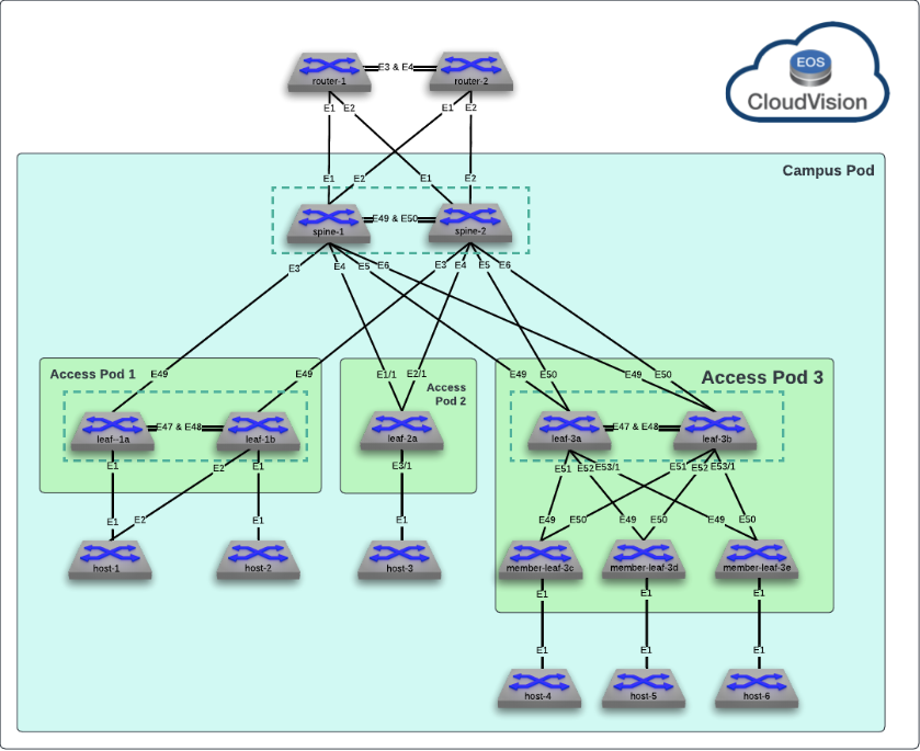
The base topology of the ATD is a typical campus deployment with a "spline" layer in an MDF and closet/IDF switches in Access Pods. We will be focusing on Access Pod 1 and 3.
Lab Tasks
Step 1 - Onboard
Devices managed by CloudVision Studios must be onboarded before any configuration changes take place. This allows users to define a subset of their devices to be managed by Studios if they wish. This initial step is done via. the built-in Inventory and Topology Studio.
Inventory & Topology Studio
-
Click on CVP on the lab landing page to access CloudVision Portal.

-
Click Provisioning (the wrench 🔧) on the left menu bar.
-
Click Studios on the left menu.
-
Click Create Workspace and name it
inventory.
Workspaces can be any name. Naming them logically helps other users in CloudVision recognize what your studio edit is doing at a glance.
-
Click Inventory and Topology under Essential Studios (notice your Workspace in the drop-down).

-
Click the Network Updates tab.
???+ note Any new device added to CloudVision will automatically be picked up as a device that can be managed via. Studios. Including Zero Touch Provisioning (ZTP) devices.
-
Click the top select all toggle next to Update. Then click Accept Updates, Accept, then Review Workspace.

-
Click Submit Workspace
Success
Your devices are now onboarded into CloudVision Studios!!
Step 2 - Build a Campus
In this lab we are building a campus network for our company’s office building on Park Avenue. This company has several campus sites in their network, this being one of them (site one).
In this building, the main distribution frame (MDF) resides in the basement, while the intermediate distribution frames (IDF) reside in the first and second floors.
This physical diagram aligns with the logical topology above, and is based on the Arista UCN architecture (1) .

Our managers have instructed us to create isolated VLANs for Wireless and Wired Data flows. We have decided to maintain the same VLAN for wireless and have unique VLANs per floor for wired.
The diagram below depicts the logical topology we will build towards.
Logical Diagram

Create the Campus
A campus is a logical grouping of devices that share L2/L3 assignments. You can assign multiple buildings to a campus, or create multiple "campuses" if you desire L2/L3 separation.
-
Navigate back to Provisioning ➡️ Studios.
-
Click Create Workspace and create a new workspace called
campus-spline.Tip
A “spline” is a main aggregation point in which distributed switches connect to. This can also be called a "spine" in the context of a campus network.
-
Turn off the
Active Studiostoggle to show the out of the box Studios.
-
Find and click the
Campus Fabricstudio by searching or scrolling down.
-
Expand Device Selection and hover over All Devices, to see all the devices available to us in Studios by importing them in Step 1.

-
Click + Add Campus and enter
Park Ave. -
Click the right arrow toggle > to enter the build screen.

Note
Here you will see the primary configuration options built into the Campus Studio. We can see the Fabric Type (layer-2 MLAG), define VLANs, configure Spline and Pod switches.
-
Assign the devices in our Park Ave campus to this Studio. This is useful if you have a large number of switches in your tenant, as it limits what is shown in this Studio as it is configured. Under Assigned Devices, select the
leaf-1[a,b],leaf-3[a,b],member-leaf-3candspine-[1,2].
Add VLANs
Referencing the logical diagram above, we see there are three VLANs that we need to create.
| VLAN ID | Name | SVI Virtual IP |
|---|---|---|
| 10 | S1-Wireless | 10.0.10.1 |
| 11 | S1-Floor1-Data | 10.0.11.1 |
| 12 | S1-Floor2-Data | 10.0.12.1 |
-
Click + Add VLAN.
-
Add VLANs based on the three rows in the table above. Think of these as the VLANs global to your Campus.

Warning
Leave IP Helper and VRF empty. VLANs will be created in Default VRF.
Configure Splines
Spline1
-
Below the VLAN section, click Add Spline.
-
Type spine in the text field to search for
spine-1and select it.
-
Click the
>right arrow next to spine-1 to enter that devices configuration area. -
For spine-1 define the following:
-
MLAG Role:
Primary -
VLAN Configuration below ⬇️
VLAN ID IP Address & Mask IP Address Role 10 10.0.10.2/24 Primary 11 10.0.11.2/24 Primary 12 10.0.12.2/24 Primary -

Spline2
-
Click Campus:Park Ave ∨ in the top menu bar to go back to the main screen, and add spine-2 as another spline device

-
Click the > arrow next to spine-2 to enter that devices configuration area.
-
Define the following for spine-2
-
MLAG Role:
Secondary -
VLAN Configuration below ⬇️
VLAN ID IP Address & Mask IP Address Role 10 10.0.10.3/24 Primary 11 10.0.11.3/24 Primary 12 10.0.12.3/24 Primary -
Tip
The IP Address Role relates to configuring a secondary device IP on a single L2 VLAN. It does not reference the MLAG role defined for the shared SVI.
Submit Changes
-
Click Review Workspace in the top right corner.
-
Click Submit Workspace.
The Studio will now automatically generate a Task, and assign it to a Change Control for you.
-
Click View Change Control.
-
Click Review and Approve.
-
Take a look at the CLI that the Studio automatically generated based on the configuration defined in the UI.

-
Click the Execute immediately toggle, then click Approve and Execute.
Checking our work - Splines
Let’s review our work so far on the spline (MDF) switches before we jump into the leaf (IDF) switches.
- Hover over the two switch icons under the magnifying glass and click Devices to view the device Inventory within CloudVision
-
Click on the blue hyperlink for
spine-1Info
Here you can see a device specific view of the telemetry information with CloudVision for spine-1. Compliance States, Processes, Table States, Environmentals, Interfaces Stats, Flow information, and Configurations.
-
Click Configuration under System

- The default view will show the Running Config
- Click the top
Configuration changehyperlink. This will show the current running configuration compared to the running configuration prior to the latest change. We are able to see that our latest Studio submission changed the running-config on the device to what we configured.
Success
Validation complete
Step 3 - Configure Leaf Pods
- Click Provisioning ➡️ Studios
- Click Create Workspace
- Name it
campus-leaf - Navigate back to the Campus Fabric studio and click the
>next to the campus you previously created (Park Aveif you followed steps above) - Scroll down to the Pods section and click + Add Pod
- Name the first
s1-pod1by typing in the name and hitting enter. - Repeat, and name the second
s1-pod3
- Click the
>arrow next to s1-pod1 to configure the first leaf pod - Click + Add Campus Leaf Device
a. Add
leaf-1awith Primary MLAG role (wait for the prompt and click Confirm) b. Addleaf-1bwith Secondary MLAG role (wait for the prompt and click Confirm)
- Click Add Pod VLAN and add
VLAN 10andVLAN 11tos1-pod1 - Click the
∨arrow next to Campus-Pod to navigate tos1-pod3 - Repeat what we did in step 9 to add leaf devices for pod3
a. Add
leaf-3awith Primary MLAG role (wait for the prompt and click Confirm) b. Addleaf-3bwith Secondary MLAG role (wait for the prompt and click Confirm) c. Addmember-leaf-3cwith Member MLAG role (wait for the prompt and click Confirm)
-
Add
VLAN 10andVLAN 12as the Pod Specific VLAN!!!! tip Leaving the Pod Specific VLAN undefined will add all VLANs defined at the Campus to the pod. Defining VLANs specific to a Pod will prune VLANs as necessary.
-
Click Review Workspace
- Notice the configuration the Studio automatically generates for the leaf switches.
- Click Submit Workspace to automatically create the Task & Change Control
-
Click View Change Control ➡️ Review and Approve
Notice how the Execute immediately toggle remains on, this is a per-user configuration in CloudVision.
-
Click Approve and Execute
Success
Your campus leaf layer 🍃 is configured!!
Step 4 - Configure Host Uplinks
We have successfully configured the campus fabric, the next step is to configure access to the downstream devices (red circles below). We will use another built-in Studio to accomplish this-–Interface Configuration.
Our downstream hosts have two NICs, support LACP and operate on VLANs respective to their floor.
In many cases, campus devices are single-homed, this lab illustrates a resilient connection for a critical device (manufacturing controls, medical cart, wireless AP). As well as a member leaf (added port density in a closet) connected to a single-homed device (phone, workstation, etc.)

Create Interface Profiles
- Click Provisioning ➡️ Studios
- Create a new workspace called
campus-devices - Click Interface Configuration
If you don’t see the Studio, make sure Active Studios is toggled off
- Click + Add Profile
- Enter
Floor1 LACP-Dataand hit enter - Edit the following configuration (leave the rest as the default)
| Profile Description | Access VLAN ID | Port Channel Group | Enable MLAG |
|---|---|---|---|
| VLAN11 - Dual-homed devices | 11 | 1 | Yes |
- Click Interface Configuration again on the top left
- Enter
Floor2 Non-LACP-Dataand hit enter - Edit the following configuration (leave the rest as the default)
| Profile Description | Access VLAN ID |
|---|---|
| VLAN12 - Single-homed devices | 12 |
Assign Profiles
- Click the
>next toleaf-1ain the Device area - On the Ethernet1 row, under
Enabledselect Yes and for the Profile pick Floor1 LACP-Data. - Click the ∨ drop-down next to
device:leaf-1aand selectleaf-1b - On the Ethernet2 row, under Enabled select Yes and for the Profile pick Floor1 LACP-Data.
- For the Ethernet1 row, under Enabled select Yes and for the Profile pick Floor2 Non-LACP-Data.
- Click Review Workspace
- Review the configuration the Studio generated for the leaf switches
- Click Submit Workspace to automatically create the Task & Change Control
- Click View Change Control ➡️ Review and Approve
- Click Approve and Execute
Step 5 - Configure Hosts
Normally this would be dependent on the device itself (i.e. IP phone), but since we are using Arista EOS as our hosts, the necessary configuration will be pasted via CLI.
In this example we are configuring VLAN aware hosts (host-1) and routed ports on an access VLAN (host-4) to illustrate different client scenarios.
- Navigate to the lab landing page (go here if you forgot how).
- Click
host-1in the network diagram to open the CLI to that device (credentials at the bottom of the page). This is our dual-homed host.
- Copy the following by clicking the copy icon on the top right of the box below
configure terminal
vlan 11
interface vlan11
ip address 10.0.11.10/24
ip route 0/0 10.0.11.1
interface Port-Channel1
   switchport access vlan 11
   spanning-tree portfast
interface Ethernet1
   channel-group 1 mode active
interface Ethernet2
   channel-group 1 mode active
wr
!
- Paste into the
host-1terminal window by right clicking and selectingpaste as plain text - Navigate back to the main topology view and click
host-4to open its terminal. This is our single homed host. - Copy the following by clicking the copy icon on the top right of the box below
- Paste into the
host-4terminal window by right clicking and selectingpaste as plain text
Verification
We will now execute some tests to validate our configuration, as well as evaluate the power of CloudVision 💪.
Inter-VLAN Routing Test
- Navigate to the cli of
host-1 - Copy the following by clicking the copy icon on the top right of the box below
- Paste into the terminal of
host-1to test inter-VLAN routing tohost-4
Simple test right? If you got a response (you should have), you have proven that we have a working layer-2|3 fabric that was built entirely via Studios with no prior CLI knowledge required.
Device Simulation Test
- While still on
host-1, paste the following into the CLI (it will look hung, but it is working)
ethxmit is a powerful traffic generator tool bundled with Arista EOS (notice how we also have bash 😁). This test simulates a continuous broadcast to host-4 with 1000 unique source mac addresses. Hit
ctrl-cto exit.
- Navigate back to CloudVision (click the CloudVision logo in the main topology view)
- Click Devices ➡️ Inventory ➡️ spine-1
- Scroll down to Switching and click MAC Address Table
Notice how the entire MAC table is visible in CloudVision, without having to CLI into the device.
- In the top header bar click compare against 1hr ago

- Observe how CloudVision is aware of current and previous entries in the MAC table, as well as providing contextual highlighting of adds/changes.

- Click on any MAC address in the table
- Review the detailed MAC information provided by CloudVision.

Topology View
Another handy feature of CloudVision Studios is that it auto-tags your devices to create an interactive network diagram for you. Follow these steps to see the topology feature of CloudVision.
- Click Topology in the left navigation pane
- Double click on the square Park Ave grouping of devices
- Expand all boxes in that campus to view the auto-grouping of devices into a topology
- In the Overlay drop-down, select
VLANs - Observe the visual overlay of the VLANs traversing network links

Success
Lab Complete!